CNC ROUTER

Jumat, 16 Maret 2012

smk6bandung.com

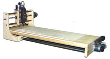
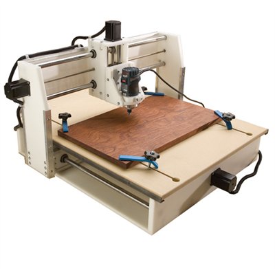
A CNC wood router is a Numerical control tool that creates objects from wood. Parts of a project can be designed in the computer with a CAD/CAM program, and then cut automatically using a router to produce a finished part.
The CNC router works like a printer. Work is composed on a computer and then the design or drawing is sent to the CNC router for the hard copy. This outputs a 3-dimensional copy of the work. The CNC router uses a cutting tool instead of an ink jet. The cutting tool is generally a router but other cutters can be used as well.
The CNC works on the Cartesian coordinate system (X, Y, Z) for 3D motion control. CNC stands for computer numerical control. This gives the computer a printer-like ability to drive a CNC machine to make parts.
The CNC Router is ideal for hobbies, engineering prototyping, product development, art, robotic education, and production work.

Contents

Operation

A CNC wood router uses CNC (computer numerical control) and is similar to a metal CNC mill with the following differences:
  • The wood router typically spins faster — with a range of 13,000 to 24,000 RPM
  • Professional quality machines frequently use surface facing tools up to 3" in diameter or more, and spindle power from 5 to 15 horsepower. Machines capable of routing heavy material at over a thousand inches per minute are common.
  • Some machines use smaller toolholders MK2 (Morse taper #2 - on older machines), ISO-30, HSK-63 or the tools just get held in a collet tool holder affixed directly to the spindle nose. ISO-30 and HSK-63 are rapid-change toolholding systems. HSK-63 has begun to supplant the ISO-30 as the rapid change standard in recent years.
A wood router is controlled in the same way as a metal mill, but there is a lot of CAM and CAD software like Artcam, Mastercam, Bobcad, and Featurecam specifically for wood routers.
Wood routers are frequently used to machine other soft materials such as plastics at high speed.
Typical three-axis CNC wood routers are generally much bigger than their metal shop counterparts. 5' x 5', 4' x 8', and 5' x 10' are typical bed sizes for wood routers. They can be built to accommodate very large sizes up to, but not limited to 12' x 100'. The table can move, allowing for true three axis (xyz) motion, or the gantry can move, which requires the third axis to be controlled by two slaved servo motors.

[edit] Features

[edit] Separate heads

Some wood routers have multiple separate heads that can come down simultaneously or not. Some routers have multiple heads that can run complete separate programs on separate tables all while being controlled by the same interface.

[edit] Dust collection

The wood router typically has 6"-10" air ducts to suck up the wood chips/dust created. They can be piped to a stand-alone or full shop dust collection system.
Some wood routers are specialized for cabinetry and have many drills that can be programmed to come down separately or together. The drills are generally spaced 32 mm apart on centres - a spacing system called 32 mm System. This is for the proper spacing of shelving for cabinets. Drilling can be vertical or horizontal (in the Y or X axis from either side/end of the workpiece) which allows a panel to be drilled on all four edges as well as the top surface. Many of these machines with large drilling arrays are derived from CNC point-to-point borers.

Securing the workpiece

Suction systems

A typical CNC wood router with suction holes visible
The wood router typically holds wood with suction through the table or pods that raise the work above the table. Pods may be used for components which require edge profiling (or undercutting), are manufactured from solid wood or where greater flexibility in production is required. This type of bed requires less extraction with greater absolute vacuum.
A second type hold down uses a spoil board. This allows vacuum suction through a low density table and allows the placement of parts anywhere on the table. These types of tables are typically used for nest-based manufacturing (NBM) where multiple components are routed from a single sheet. This type of manufacturing precludes edge drilling or undercut edge work on components.
Vacuum pumps are required with both types of tables where volume and "strength" are determined based on the types of materials being cut.
Sabtu, 10 Maret 2012

kode kode program mesin CNC

Kode Standar Mesin CNC
Mesin CNC hanya dapat membaca kode standar yang telah disepakati oleh industri yang membuat mesin CNC. Dengan kode standar tersebut, pabrik mesin CNC dapat menggunakan PC sebagai input yang diproduksi sendiri atau yang direkomendasikan. Kode standar pada mesin CNC yaitu :
Mesin Bubut
Fungsi G
G00 Gerakan cepat
G01Interpolasi linear
G02/G03 Interpolari melingkar
G04 Waktu tinggal diam.
G21 Blok kosong
G24 Penetapan radius pada pemrograman harga absolut
G25/M17 Teknik sub program
G27 Perintah melompat
G33 Pemotongan ulir dengan kisar tetap sama
G64 Motor asutan tak berarus
G65 Pelayanan kaset
G66 Pelayanan antar aparat RS 232
G73 Siklus pemboran dengan pemutusan tatal
G78 Siklus penguliran
G81 Siklus pemboran
G82 Siklus pemboran dengan tinggal diam.
G83 Siklus pemboran dengan penarikan
G84 Siklus pembubutan memanjang
G85 Siklus pereameran
G86 Siklus pengaluran
G88 Siklus pembubutan melintang
G89 Siklus pereameran dengan tinggal diam.
G90 Pemrograman harga absolut
G91 Pemrcgraman harga inkremental
G92 Pencatat penetapan
G94 Penetapan kecepatan asutan
G95 Penetapan ukuran asutan
G110 Alur permukaan
G111 Alur luar
G112 Alur dalam
G113 Ulir luar
G114 Ulir dalam
G115 Permukaan kasar
G116 Putaran kasar
Fungsi M
M00 Berhenti terprogram
M03 Sumbu utama searah jarum jam
M05 Sumbu utama berhenti
M06 Penghitungan panjang pahat, penggantian pahat
M08 Titik tolak pengatur
M09 Titik tolak pengatur
Ml7 Perintah melompat kembali
M22 Titik tolak pengatur
M23 Titik tolak pengatur
M26 Titik tolak pengatur
M30 Program berakhir
M99 Parameter lingkaran
M98 Kompensasi kelonggaran / kocak Otomatis
Mesin Frais
Fungsi G
G00 Gerakan cepat
G01 Interpolasi lurus
G02 Interpolasi melinqkar searah iarum Jam
G03 Interpolasi melinqkar berlawanan arah jarum jam
G04 Lamanya tingqal diam.
G21 Blok kosonq
G25 Memanqqil sub program
G27 Instruksi melompat
G40 Kompensasi radius pisau hapus
G45 Penambahan radius pirau
G46 Pengurangan radius pisau
G47 Penambahan radius pisau 2 kali
G48 Penguranqan radius pisau 2 kali
G64 Motor asutan tanpa arus (Fungsi penyetelan)
G65 Pelavanan pita magnet (Fungsi penyetetan)
G66 Pelaksanaan antar aparat dengan RS 232
G72 Siklus pengefraisan kantong
G73 Siklus pemutusan fatal
G74 Siklus penguliran (jalan kiri)
G81 Siklus pemboran tetap
G82 Siklus pemboran tetap dengan tinj diam
G83 Siklus pemboran tetap dengan pembuangantatal
G84 Siklus penquliran
G85 Siklus mereamer tetap
G89 Siklus mereamer tetap denqan tinqqal diam.
G90 Pemroqraman nilai absolut
G91 Pemroqraman nilai inkremental
G92 Penqqeseran titik referensi
Fungsi M
M00 Diam
M03 Spindel frais hidup.searahjarumjam
M05 Spindel frais mat!
M06 Penggeseran alat, radius pisau frais masuk
M17 Kembali ke program pokok
M08 Hubungan keluar
M09 Hubungan keluar
M20 Hubungan keluar
M21 Hubungan keluar
M22 Hubungan keluar
M23 Hubungan keluar
M26 Hubungan keluar- impuls
M30 Program berakhir
M98 Kompensasi kocak / kelonggaran otomatis
M99 Parameter dari interpolasi melingkar (dalam hubungan dengan G02/303)
Tanda Alarm
A00 Salah kode G/M
A01 Salah radius/M99
A02 Salah nilaiZ
A03 Salah nilai F
A04 Salah nilai Z
A05 Tidak ada kode M30
A06 Tidak ada kode M03
A07 Tidak ada arti
A08 Pita habis pada penyimpanan ke kaset
A09 Program tidak ditemukan
A10 Pita kaset dalam pengamanan
A11 Salah pemuatan
A12 Salah pengecekan
A13 Penyetelan inchi/mm dengan memori program penuh
A14 Salah posisi kepala frais / penambahan jalan dengan LOAD ┴ / M atau ┤ / M
A15 Salah nilai Y.
A16 Tidak ada nilai radius pisau frais
A17 Salah sub program
A18 Jalannya kompensasi radius pisau frais lebih kecil dari nol

MEMBUAT MESIN CNC ROUTER SENDIRI


Membuat sendiri  mesin CNC sekarang ini sudah menjadi hobi sebagian orang di dunia – termasuk di Indonesia. Mungkin karena tantangan yang melibatkan keterampilan pertukangan, pengetahuan elektronika dan software  membuat orang-orang penasaran ingin bisa membuat mesin CNC sendiri. Ditambah lagi dengan kegembiraan kalau sudah berhasil membuat mesin CNC sendiri, sebab seseorang bisa memotong, membentuk, mengukir aneka kreasi baik 2 dimensi maupun 3 dimensi secara otomatis berdasarkan gambar dari komputer.
Mesin CNC yang umum dibuat oleh para hobbyist adalah yang memiliki 3 axis atau 3 sumbu gerakan, yaitu X, Y dan Z. Atau yang dapat bergerak ke kiri-kanan, maju-mundur dan naik-turun. Kira-kira yang seperti ini:
Pada bagian sumbu Z (naik-turun) kita menyimpan sebuah tool yang berupa rotary tool seperti mesin bor, alat grafir, router, spindle atau alat optik seperti mata laser atau alat extruder. Tool ini adalah alat utama pada mesin CNC, bagian lain pada mesin tugasnya adalah mengarahkan tool ini pada titik kerja yang dituju – pada bahan.
Penggerak pada setiap sumbu CNC adalah motor. Misalnya menggunakan servo atau motor stepper. Yang paling populer digunakan pada DIY CNC adalah stepper. Biasanya stepper dipakai pada printer, mesin fax, scanner. Gerakan stepper yang konstan (step demi step) sangat cocok untuk menciptakan hasil kerja yang cukup akurat.
Bagian-bagian Pada Mesin CNC:
  • Tool (router, spindle, laser, dll)
  • Leadscrew (batang ulir)
  • Rod (batang poros / as)
  • Bearing
  • Stepper
  • Motor coupling
  • Rangka (Misalnya: MDF, multiplex, alumunium, nylon, dsb)
  • Stepper driver & controller (elektronik)